The ER model defines the conceptual view of a database. It works around real-world entities and the associations among them. At view level, the ER model is considered a good option for designing databases.
Entity
An entity can be a real-world object, either animate or inanimate, that can be easily identifiable. For example, in a school database, students, teachers, classes, and courses offered can be considered as entities. All these entities have some attributes or properties that give them their identity.
An entity set is a collection of similar types of entities. An entity set may contain entities with attribute sharing similar values. For example, a Students set may contain all the students of a school; likewise a Teachers set may contain all the teachers of a school from all faculties. Entity sets need not be disjoint.
Attributes
Entities are represented by means of their properties, called attributes. All attributes have values. For example, a student entity may have name, class, and age as attributes.
There exists a domain or range of values that can be assigned to attributes. For example, a student's name cannot be a numeric value. It has to be alphabetic. A student's age cannot be negative, etc.
Types of Attributes
Simple attribute − Simple attributes are atomic values, which cannot be divided further. For example, a student's phone number is an atomic value of 10 digits.
Composite attribute − Composite attributes are made of more than one simple attribute. For example, a student's complete name may have first_name and last_name.
Derived attribute − Derived attributes are the attributes that do not exist in the physical database, but their values are derived from other attributes present in the database. For example, average_salary in a department should not be saved directly in the database, instead it can be derived. For another example, age can be derived from data_of_birth.
Single-value attribute − Single-value attributes contain single value. For example − Social_Security_Number.
Multi-value attribute − Multi-value attributes may contain more than one values. For example, a person can have more than one phone number, email_address, etc.
These attribute types can come together in a way like −
- simple single-valued attributes
- simple multi-valued attributes
- composite single-valued attributes
- composite multi-valued attributes
Entity-Set and Keys
Key is an attribute or collection of attributes that uniquely identifies an entity among entity set.
For example, the roll_number of a student makes him/her identifiable among students.
Super Key − A set of attributes (one or more) that collectively identifies an entity in an entity set.
Candidate Key − A minimal super key is called a candidate key. An entity set may have more than one candidate key.
Primary Key − A primary key is one of the candidate keys chosen by the database designer to uniquely identify the entity set.
Relationship
The association among entities is called a relationship. For example, an employee works_at a department, a student enrolls in a course. Here, Works_at and Enrolls are called relationships.
Relationship Set
A set of relationships of similar type is called a relationship set. Like entities, a relationship too can have attributes. These attributes are called descriptive attributes.
Degree of Relationship
The number of participating entities in a relationship defines the degree of the relationship.
- Binary = degree 2
- Ternary = degree 3
- n-ary = degree
Mapping Cardinalities
Cardinality defines the number of entities in one entity set, which can be associated with the number of entities of other set via relationship set.
One-to-one − One entity from entity set A can be associated with at most one entity of entity set B and vice versa.
One-to-many − One entity from entity set A can be associated with more than one entities of entity set B however an entity from entity set B, can be associated with at most one entity.
Many-to-one − More than one entities from entity set A can be associated with at most one entity of entity set B, however an entity from entity set B can be associated with more than one entity from entity set A.
Many-to-many − One entity from A can be associated with more than one entity from B and vice versa.
Let us now learn how the ER Model is represented by means of an ER diagram. Any object, for example, entities, attributes of an entity, relationship sets, and attributes of relationship sets, can be represented with the help of an ER diagram.
Entity
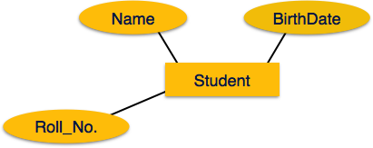
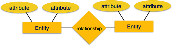
Entities are represented by means of rectangles. Rectangles are named with the entity set they represent.

Attributes
Attributes are the properties of entities. Attributes are represented by means of ellipses. Every ellipse represents one attribute and is directly connected to its entity (rectangle).
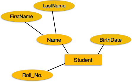
If the attributes are composite, they are further divided in a tree like structure. Every node is then connected to its attribute. That is, composite attributes are represented by ellipses that are connected with an ellipse.
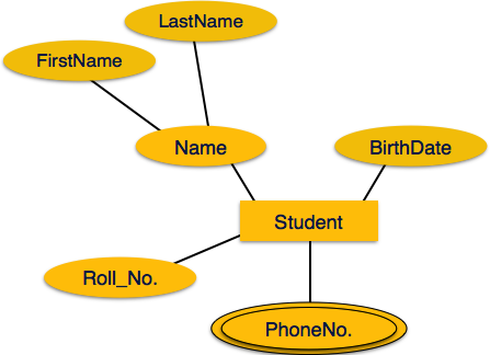
Multivalued attributes are depicted by double ellipse.
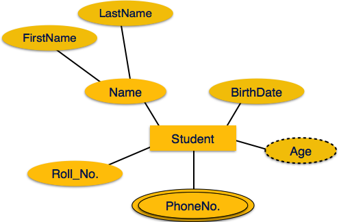
Derived attributes are depicted by dashed ellipse.
Relationship
Relationships are represented by diamond-shaped box. Name of the relationship is written inside the diamond-box. All the entities (rectangles) participating in a relationship, are connected to it by a line.
Binary Relationship and Cardinality
A relationship where two entities are participating is called a binary relationship. Cardinality is the number of instance of an entity from a relation that can be associated with the relation.
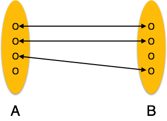
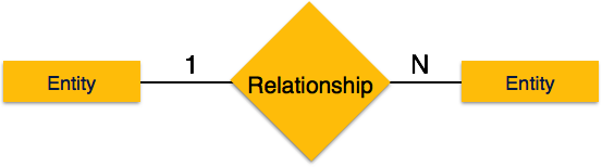
One-to-one − When only one instance of an entity is associated with the relationship, it is marked as '1:1'. The following image reflects that only one instance of each entity should be associated with the relationship. It depicts one-to-one relationship.

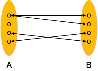
One-to-many − When more than one instance of an entity is associated with a relationship, it is marked as '1:N'. The following image reflects that only one instance of entity on the left and more than one instance of an entity on the right can be associated with the relationship. It depicts one-to-many relationship.
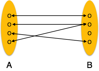
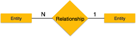
Many-to-one − When more than one instance of entity is associated with the relationship, it is marked as 'N:1'. The following image reflects that more than one instance of an entity on the left and only one instance of an entity on the right can be associated with the relationship. It depicts many-to-one relationship.
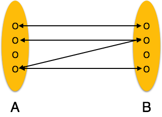
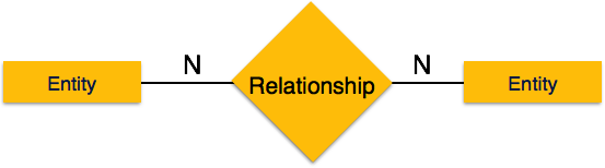
Many-to-many − The following image reflects that more than one instance of an entity on the left and more than one instance of an entity on the right can be associated with the relationship. It depicts many-to-many relationship.
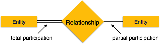
Participation Constraints
Total Participation − Each entity is involved in the relationship. Total participation is represented by double lines.
Partial participation − Not all entities are involved in the relationship. Partial participation is represented by single lines.
No comments:
Post a Comment